
Fine Blanking Dies: Design, Build, Tryout and Maintenance
A fine blanking die must coordinate cutting geometry, blank holding, counterpressure, strip flow and maintenance access with the selected press. We define the tooling boundary from your part drawing and acceptance criteria.
What Our Die Design Covers
- Cutting-edge clearance and rounded (V-ring) impingement geometry for shear-face control
- Stripper plate design and stripper force calculation
- Counter-pressure (ejector) pad layout and force curve
- Punch and die material selection (tool steel grade, coating) for expected volume
- DFM (Design for Manufacturability) feedback on your part drawing before tooling starts
- Tryout support and shear-face sample validation before mass production
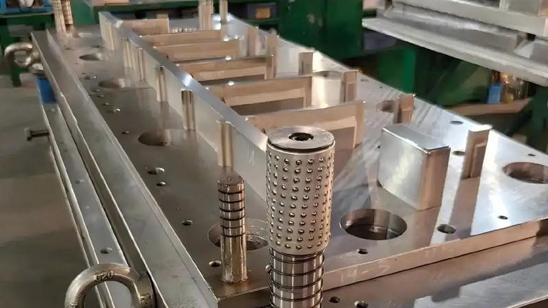
From Part Drawing to Validated Die
DFM Review
We review your 2D/3D drawing for fine-blankability - corner radii, hole-to-edge distance, material grade.
Die Layout & Simulation
Cutting-edge, stripper and counter-pressure system are designed and reviewed against press tonnage capability.
Tool Manufacturing
Precision grinding and wire-EDM manufacture of punches, dies and strippers to design tolerance.
Tryout & Sample Approval
Die tryout on our press, shear-face and dimensional sample sent for your approval before shipment.
Inputs Needed Before Die Design Starts
- Dimensioned drawing, 3D model and critical datums
- Material grade, thickness, hardness and supply condition
- Annual volume, lot size and target production requirement
- Cut-face, burr, flatness and downstream-process requirements
- Press platform, shut height, table envelope and available force functions
Plan Beyond First-Off Samples
Tool access, insert strategy, sharpening limits, spare punches, inspection records and maintenance intervals should be agreed before build. See the die maintenance checklist and the fine blanking process guide.
Have a part drawing ready?
Send your 2D/3D drawing and target volume - our tooling engineers will confirm feasibility and quote die design and build.